As built
Rev B, assembled by JLCPCB.
Photographed before the first flash. Firmware 1.2 is now running on it and advertising over Bluetooth.
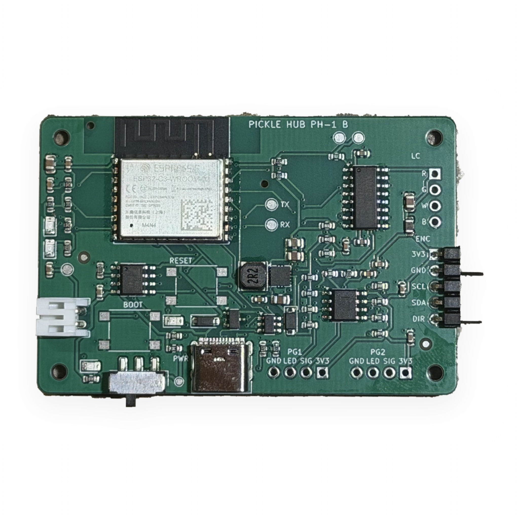


One 66 × 44 mm, two-layer PCB runs the whole kit: an ESP32-C3 with Bluetooth and Wi-Fi, USB-C charging, a buck-boost supply, a 24-bit load-cell front end, two photogate comparators and the encoder port. All 68 SMT parts are JLCPCB basic or extended; DRC passes with zero violations.
Photographed before the first flash. Firmware 1.2 is now running on it and advertising over Bluetooth.
Right-angle 2.54 mm headers on two edges; one Dupont ribbon pack wires the whole kit.
| Header | Pins | Goes to |
|---|---|---|
| ENC | 3V3 · GND · SCL · SDA · DIR | AS5600 module in the cart or the spindle flange |
| LC | 3V3A · A+ · A− · GND (R G W B) | 20 kg bar load cell on the cart nose or the hanging hook |
| PG1 / PG2 | 3V3 · SIG · LED · GND | Photogate forks |
| BAT | JST-PH 2-pin | 2000 mAh pouch under the board |
| USB-C | 5 V · D+ · D− | Charging, flashing, wired dashboard |
| GPIO | Function | Note |
|---|---|---|
| IO0 / IO1 | SDA / SCL | I²C 400 kHz |
| IO2 | HX_RATE | 80 SPS default |
| IO3 | VBAT_ADC | battery divider |
| IO4 / IO5 | HX_DOUT / HX_SCK | 24-bit force |
| IO6 / IO7 | PG1 / PG2 | ISR-timestamped |
| IO8 | BLE LED | active low |
| IO9 | BOOT | zero / tare |
| IO18 / IO19 | USB | native CDC |
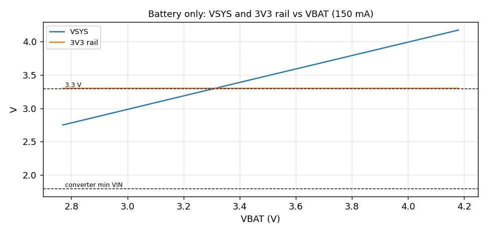
ngspice runs on the hand-over, battery range, comparator and reset paths; every IC pinout read back against its datasheet.



Order it yourself from the Gerbers, or buy the assembled board with the kit.