Photos
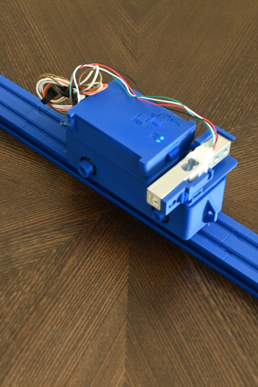
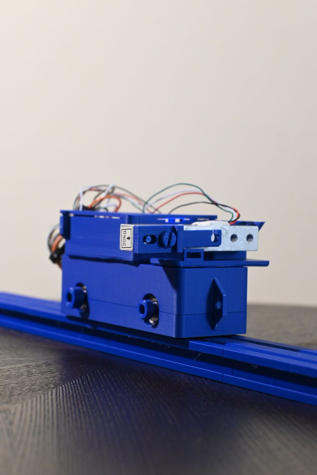
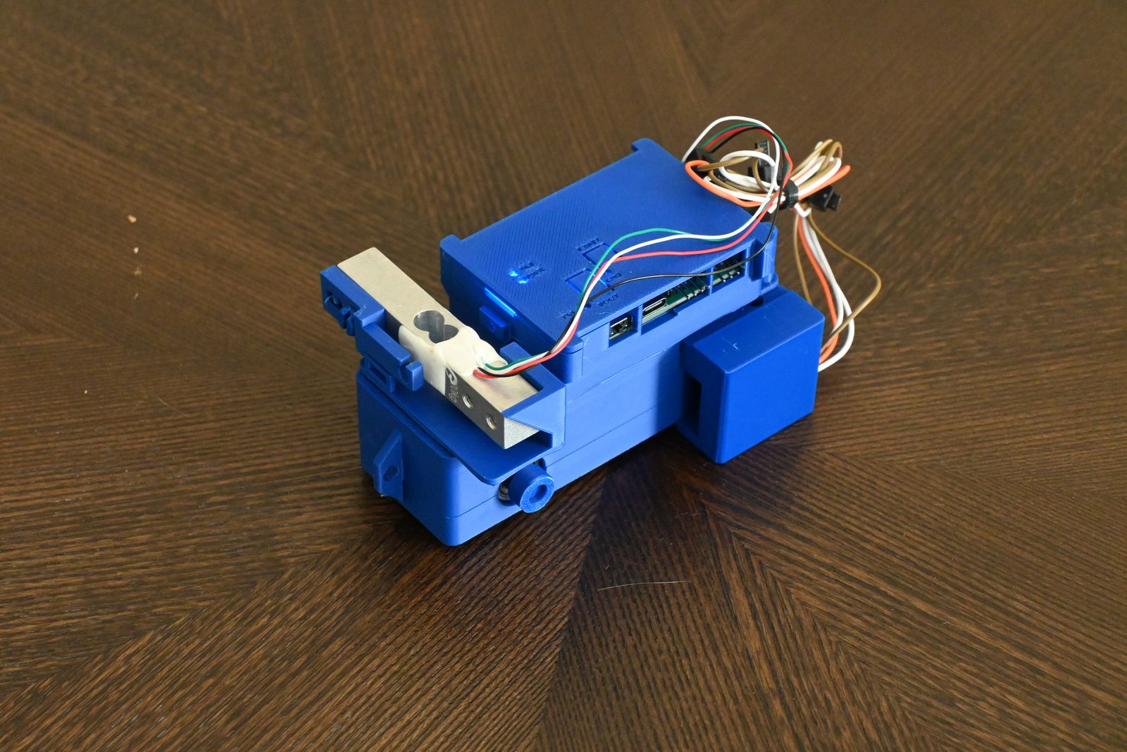
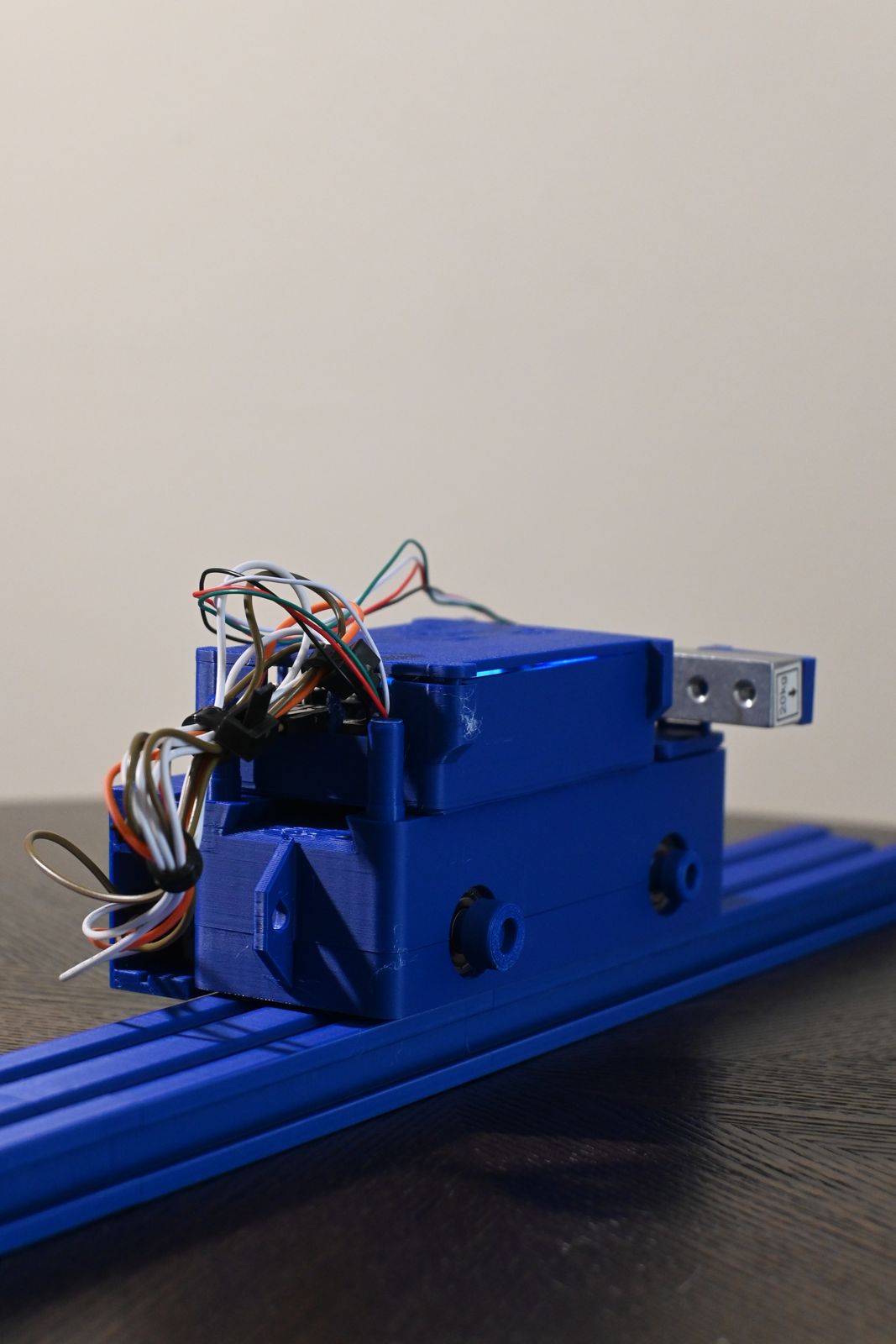
Printed, wired and rolling.
The Smart Cart and rail as they come off the printer — load cell on the nose, Hub on the deck, battery pod on the side.
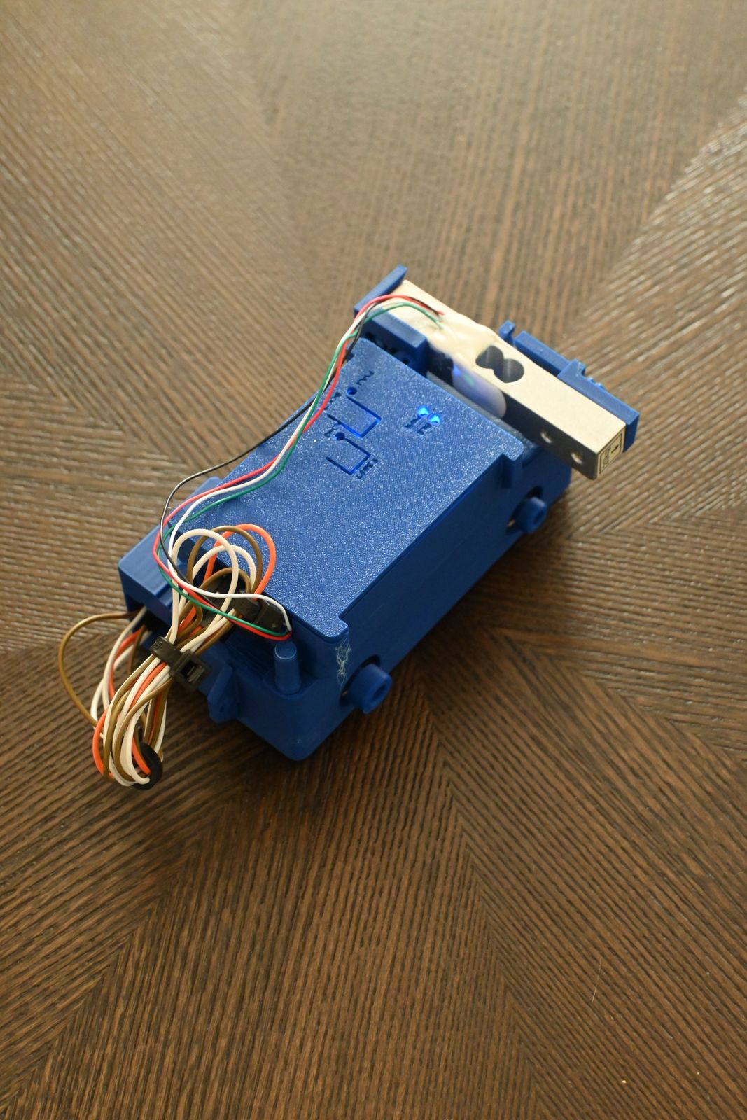
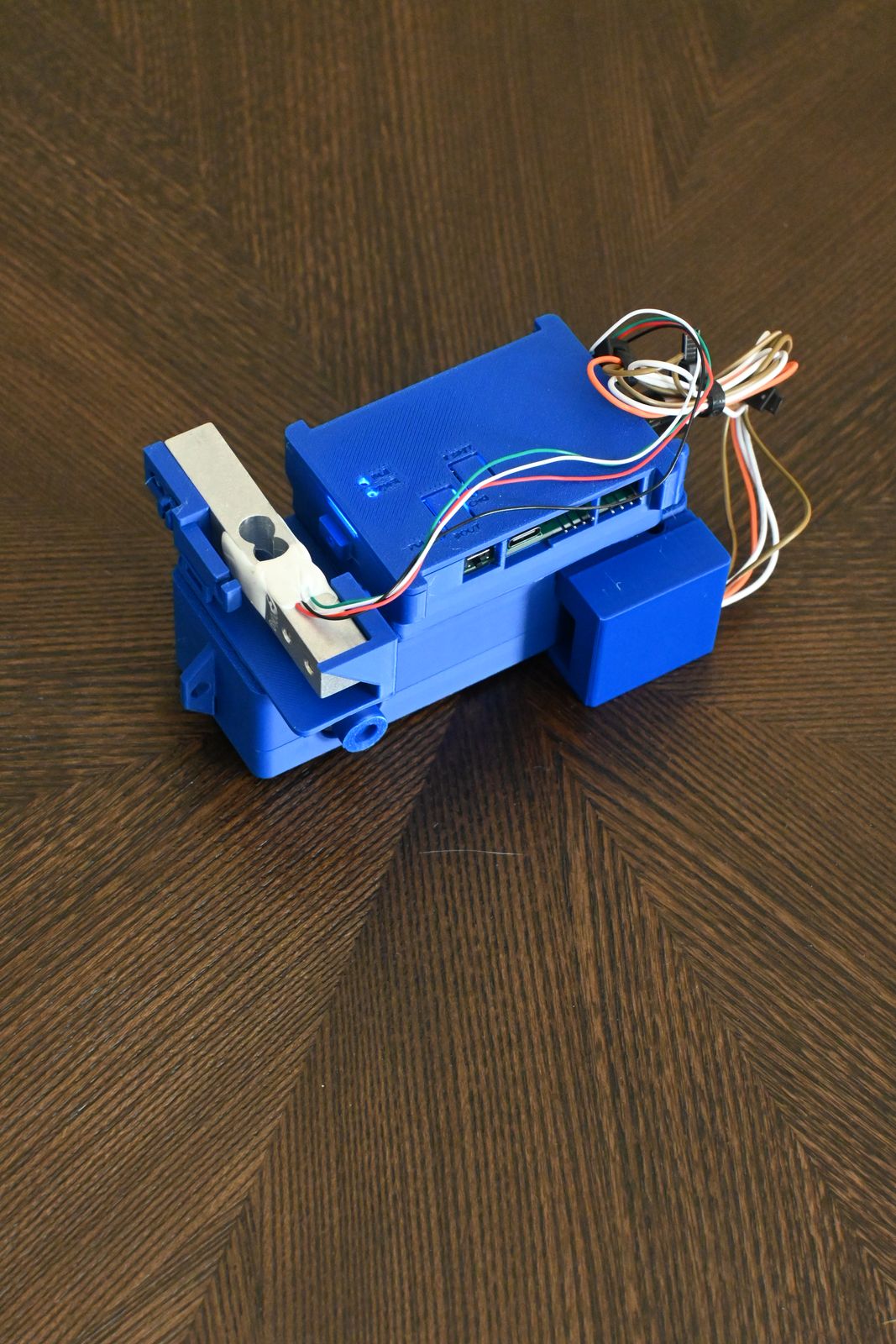
Pickle Core is one printed system: a rail that is also a stand, a cart that is also a force sensor, and a Hub that reads all of it. Spin every piece below — these are the production CAD files.
The Smart Cart and rail as they come off the printer — load cell on the nose, Hub on the deck, battery pod on the side.
Two printed halves clamp around a bench-assembled stack of 625ZZ bearings, printed roll-pin axles and V-wheels. A Ø4 mm diametric magnet in the rear axle is read by an AS5600 encoder in a slide-in holder — 4096 counts per turn, 0.02 mm per count. The Hub docks into a dovetail on the deck; the nose carries a 20 kg bar load cell with a hook bar for tension and impact. Nickel well and nut posts add calibrated mass.
A 36 × 16 mm V-groove profile in 100 mm segments — all ten fit one P1S plate — joined by dovetail tongues that drop straight into the next segment’s socket. Printed sliders in the side channels take M5 thumbscrews for feet, forks, spring ends and the clamp. Lay it flat, prop one end, or stand it in the base as the spring and torque stand.
One 66 × 44 mm board in a printed two-piece enclosure: ESP32-C3 with Bluetooth and Wi-Fi, USB-C charging for a 2000 mAh pouch cell, a buck-boost supply, a 24-bit load-cell front end, two photogate comparators and the encoder port. It streams JSON over Bluetooth and USB to a single-file dashboard — no app, no account.
A 940 nm IR LED and a filtered phototransistor sit in collimating bores across a 42 mm gap. The Hub’s LM393 comparator turns the beam into a clean edge and timestamps it to 1 µs, reporting blocked time, time between blocks and the pairing between two gates. The fork hangs beside the rail on an M5 slider, stands on the bench, or bolts to the launcher’s gate bar.
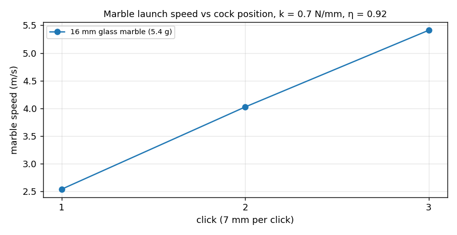
A ⅝ × 2¾ in hardware-store compression spring in a printed barrel drives a plunger with three sear positions; a thumb key releases it. The 16 mm glass marble leaves at 2.5, 4.0 or 5.4 m/s and crosses two forks 50 mm apart on the gate bar. The body pivots on its base with detents at 0°, 15°, 30°, 45° and 60°. Thirty-three engineering checks cover the spring, sear, speeds, stresses and recoil.

A spindle block clamps to the rail with four M5 sliders and carries a 5 × 50 mm steel axle in two bearings. The 120 mm platform disc presses onto it with a 31 mm spool for the cord; the same AS5600 encoder reads the spindle. Nuts in hex pockets at three radii change I by a known amount.
The end piece drops onto the rail’s last tongue; a yoke slides down its dovetail and carries a 16 mm two-half sheave on a printed D-shaft in two 3 × 8 × 4 bearings. Cord height matches the cart’s bumper line for the modified Atwood lab, and the table clamp holds the pulley at a table edge for the hanging-mass runs.
Two 6 × 50 mm extension springs hook between the rail’s spring end pieces and eyes on the cart for SHM on the track. Three segments stand in the printed base to make a 33 cm stand; the end cap’s eye hangs a spring and the mass hanger for Hooke’s law. Masses are M8 nuts and US nickels, weighed on the kit’s own scale.
Four printed parts turn the stand into a torque balance: a pivot bracket clamps to the rail’s side face like the photogate fork, a saddle holds any 25–32 mm ruler or metre stick on a knife-edge pin, and three clips hang the mass hangers at measured distances. Students find an unknown mass from a known one, then the stick’s own mass with the pivot off centre.
A Ø78 mm roller with the cart wheels’ V-rim profile rides the same grooves. Seven hex pockets per face take M8 nuts, so students shift the centre of mass off the axis, predict the rest angle on a slope, and race symmetric and offset loadings down the incline.
The Pickle Core kit ships printed, with every bought part in the box. Available to purchase on Shopify.